Import Input Data from Excel Files
Importing from Excel files allows you to upload project data structured in a generic format. It is possible to extract this data from any structural software and sort it according to the format explained below.
Three Excel spreadsheets must be uploaded:
-
1. Excel spreadsheet with coordinates: Contains node numbers, coordinates and wall identification.
-
2. Excel spreadsheet with service loads: Contains the service loads (those that will be used for the sizing of foundations) for each node in all load combinations to be considered.
-
3. Excel spreadsheet with ultimate loads: Contains the ultimate loads (those that will be used for the design of steel reinforcements) for each node in all load combinations to be considered, identifying whether the load combination is static or dynamic.
You can download the empty Excel forms from the Foundaxis website (in Project Space) or build them directly. The data must be in the first sheet of the Excel file.
Below is the structure of each required sheet:
1. Excel coodinate sheets
The figure below shows an image of a typical coordinates sheet.
 The required fields in each column are the following:
- Column 1 (Header name: Node): Node number:
- Column 2 (Header name: X): X coordinate of the Node.
- Column 3 (Header name: Y): Y coordinate of the Node.
- Column 4 (Header name: Z): Z coordinate of the Node.
- Column 5 (Header name: Type): Specifies if the node is a Column or belongs to a wall, it can take the value C(if it is a column) or W (if it is a wall).
- Column 6 (Header name: Angle): Specifies a rotation in degrees of the column with respect to the global X and Y axes.
- Column 7 (Header name: IsExtreme): Takes the value 1 if the node corresponds to an end of a wall, for the rest of the cases it is 0.
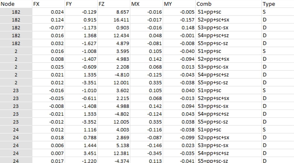
2. Excel Sheet Service Loads
The figure below shows an image of a typical ultimate loads sheet.
The required fields in each column are the following:
- Column 1 (Header name: Node): Node number:
- Column 2 (Header name: FX): Reaction Force in X of the Node.
- Column 3 (Header name: FY): Reaction Force in Y of the Node.
- Column 4 (Header name: FZ): Reaction Force in Z of the Node.
- Column 5 (Header name: MX): Moment reaction about the X axis at the node.
- Column 6 (Header name: MY): Moment reaction about the Y axis at the node.
- Column 7 (Header name: Comb): Name of the load combination.
- Column 8 (Header name: Type): takes the value S if the load combination is static or D if the load combination is dynamic. (This descriptor determines whether the evaluation of allowable stresses in foundation seal is performed for the entered static limit or for the entered dynamic limit.)
ULTIMATE LOADS EXCEL SHEET
The figure below shows an image of a typical ultimate loads sheet.
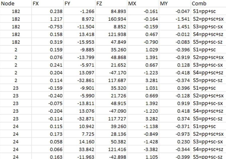
- Column 1 (Header name: Node): Node number:
- Column 2 (Header name: FX): Reaction Force at Node X.
- Column 3 (Header name: FY): Reaction Force at Node Y.
- Column 4 (Header name: FZ): Reaction Force at Node Z.
- Column 5 (Header name: MX): Moment reaction about the X axis at the node.
- Column 6 (Header name: MY): Moment reaction about the Y axis at the node.
- Column 7 (Header name: Comb): Name of the load combination.
RELEASE V1.0BC IMPORTANT NOTE: This release only supports Tonf/m or Kip/ft or kN/m units. Do not forget to use these units for coordinates, forces and moment data.